Interrupt controllers on the x86 platform are responsible for receiving interrupt signals from devices, mapping the signal to an IDT vector, and then interrupting one or more CPUs in the system with the IDT vector. The x86 platform has some extra quirks, however. First, due to limitations with the original interrupt controllers and busses used on the PC-AT, separate programmable interrupt routers were added to the platform to sit in between PCI interrupt signals and the PC-AT interrupt controllers. Second, as the x86 platform continued to progress, an entirely new set of interrupt controllers, known as Advanced Programmable Interrupt Controllers (APICs), were introduced. In order to preserve backwards compatibility, systems with APICs also still include the PC-AT interrupt controllers and either system can be used to handle interrupts on modern systems. It is even possible to use both at the same time though doing so is discouraged.
The original PC-AT included two 8259A Programmable Interrupt Controllers (PICs) chained together. As with many other aspects of the PC-AT, this setup became part of the de facto standard for the x86 platform. Each 8259A has eight interrupt input signals that are assigned to eight consecutive IDT vectors. Two PICs thus yields sixteen total interrupt inputs. On the PC-AT these signals were known as ISA IRQs 0 through 15. However, the second 8259A (known as the slave PIC) is connected to the third input pin on the first 8259A (known as the master PIC). Thus, ISA IRQ 2 is not available for device interrupts, and there are really only fifteen interrupt inputs available for device interrupts.
The original PC-AT also used an ISA bus for its devices. ISA interrupts are edge triggered and are asserted by having the device raise the signal from low to high. This inhibits sharing of ISA interrupts by multiple devices, so each ISA device requires a dedicated interrupt input on the 8259As. All PC-AT compatible systems included an ISA timer which used IRQ 0, a keyboard controller that used IRQ 1, and a real time clock which used IRQ 8. The optional floating point co-processor used IRQ 13 if it was present. When PCI was introduced, most PC-AT compatible systems included two serial ports which used IRQs 3 and 4, a floppy controller which used IRQ 6, a line printer port which used IRQ 7, a PS/2 mouse port which used IRQ 12, and two IDE controllers which used IRQs 14 and 15. This left only IRQs 5, 9, 10, and 11 for PCI interrupts to use.
To make matters even more complicated many systems included other ISA devices such as additional serial or printer ports or sound cards. Each of these additional ISA devices also required a dedicated IRQ. Sound cards, for example, often used IRQ 5. Thus, the set of IRQs available for use by PCI interrupts was not fixed. Rather, simply adding or removing an ISA peripheral could change the set across reboots. To deal with this complication, programmable interrupt routers were added.
A programmable interrupt router is used to route PCI interrupt signals to interrupt inputs on another interrupt controller. A router contains several input signals and output signals. Each output signal is hooked up to an input on an interrupt controller. Each input signal can be routed to one of the output signals. Multiple input signals can be routed to the same output signal. Multiple PCI interrupt signals can be routed to a single input signal.
System software, such as the BIOS or operating system, is responsible for programming the interrupt router. Programming the router consists of routing each input signal that is in use to an output signal. For example, a PC-AT compatible system might have the output pins from the programmable interrupt router hooked up to the interrupt lines for IRQs 3, 4, 5, 7, 9, 10, and 11 on the 8259A PICs. If IRQs 3, 4, and 7 are in use by ISA devices, then each input pin on the interrupt router must be routed to one of the IRQs 5, 9, 10, or 11. Note that routing a single input pin (also known as a PCI Link Device) to an IRQ routes all of the PCI interrupts connected to that input pin to the IRQ. That is, one can't arbitrarily route individual PCI interrupts at will. Instead, one can only route a group of PCI interrupts that are connected to an input pin. This grouping is set in the hardware and cannot be altered by system software. Also, if a system has more input pins than available IRQs, then at least some of the input pins will be routed to the same IRQ resulting in the union of all the PCI interrupts on those input pins sharing the same IRQ.
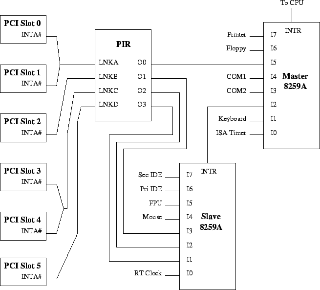
An example of using a programmable interrupt router in combination with the 8259A PICs can be found in Figure 1. On the left are six PCI slots. The INTA# pin from each slot is connected to one of the input pins on the interrupt router, which is labeled ``PIR.'' Notice that some of the PCI interrupts are wired to the same input pin on the interrupt router. For example, the first two interrupts are both connected to the LNKA input pin. The interrupt router also has four output pins that are connected to input pins on the two 8259A controllers corresponding to IRQs 5, 9, 10, and 11. Suppose that LNKA is routed to O0, LNKB is routed to O1, LNKC is routed to O2, and LNKD is routed to 00. Then the interrupts for PCI slots 0, 1, and 5 would be routed to IRQ 5. The interrupt for PCI slot 2 would be routed to IRQ 11, and the interrupts for PCI slots 3 and 4 would be routed to IRQ 10.
Many x86 systems, including most recent systems, include a second set of interrupt controllers known as APICs. In these systems, each CPU includes a local APIC which receives interrupt messages and uses them to assert interrupts on the CPU. The chipset includes one or more I/O APICs which are responsible for converting device interrupt signals into messages that are delivered to one or more local APICs.
One of the biggest differences between the 8259A PICs and I/O APICs is that the pins on I/O APICs are completely independent. With the 8259A PICs, the eight input pins are mapped to eight consecutive IDT vectors, and all of the interrupts are sent to the same CPU. I/O APICs, on the other hand, do not have any controller-wide settings. Instead, each pin is programmed independently. Each pin is assigned its own IDT vector by the operating system and can be mapped to one or more CPUs. I/O APICs can also contain a variable number of pins. Typically an I/O APIC contains 16, 24, or 32 input pins.
PCI interrupt signals are routed to I/O APIC interrupt pins in several different ways. The earliest APIC systems include a single I/O APIC with 16 input pins that simply replicate the functionality of the two 8259A PICs. In these systems, the 16 input pins are used for the 16 ISA IRQs, and PCI interrupts are routed onto the ISA IRQs using a programmable interrupt router. Most APIC systems, however, use dedicated I/O APIC input pins for PCI interrupt signals. In these systems, the first 16 pins on the first I/O APIC are used for the 16 ISA IRQs. PCI interrupt signals are connected to other input pins on the first I/O APIC (if it contains more than 16 input pins) as well as input pins on additional I/O APICs (if present). Some very recent systems have begun routing some of the PCI interrupt signals to a programmable interrupt router whose output pins are connected to a set of I/O APIC input pins that are dedicated to PCI interrupts.
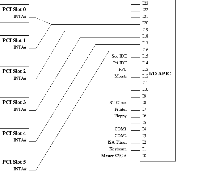
Figure 2 contains an example of a system with a 24-pin I/O APIC where the PCI interrupts are connected directly to input pins on the I/O APIC. As with the previous figure, there are six PCI slots on the left, and the INTA# pin from each slot is connected to one of the input pins on the I/O APIC. A system may still have shared PCI interrupts even when using APICs if multiple interrupt lines are connected to the same I/O APIC input pin. For example, the first two interrupts for PCI slots 0 and 1 are both connected to I20 input pin. The other interrupts are all routed to their own input pin: PCI slots 2, 3, 4, and 5 are routed to input pins I19, I18, I17, and I16, respectively.