My TS-940S Died
So, on June 5th at 05:24:25 UTC, my HF rig died.
I was casually running some S&P FT8 and responding to VK2BC on 20m, when I noticed my TX didn’t move my needles. Looking over at the radio it was powered off.
I tried turning it off and on again (no luck), and I checked the timer button (not pressed). Yep, I have fallen prey to the dreaded power supply failure.
The TS-940S is well known for having power supply issues. It’s a big honking linear with some scary big filter caps and various other lesser power supplies…
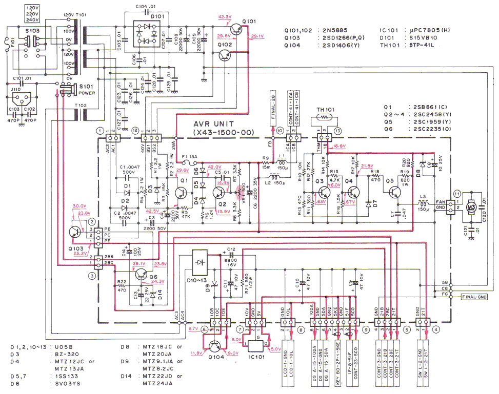
the main transformer outputs 28VAC which is rectified by a diode bridge on the heat sink, and filtered to produce about 43VDC, which is then regulated down to 28.5VDC by two beefy (but clearly not beefy enough since there’s two of ‘em) transistors on the heat sink. This is the power for the finals.
That 28.5VDC heads back to the heat sink to another pass transistor which gives us 21VDC to run the rest of the TX and RX “stuff”.
The 28VAC is further reduced by another transformer to 14VAC then rectified and filtered to about 18VDC which heads back to the heat sink to a transistor which gives us 8VDC used to run the display, and it goes back to the heat sink one last time to a regulator which provides the 5VDC that the digital bits run off.
So, there’s a lot of stuff on the big power supply heat sink. There’s a thermistor controlled fan on there which will come on even when in RX mode, because there’s so much stuff heating that block of aluminum.
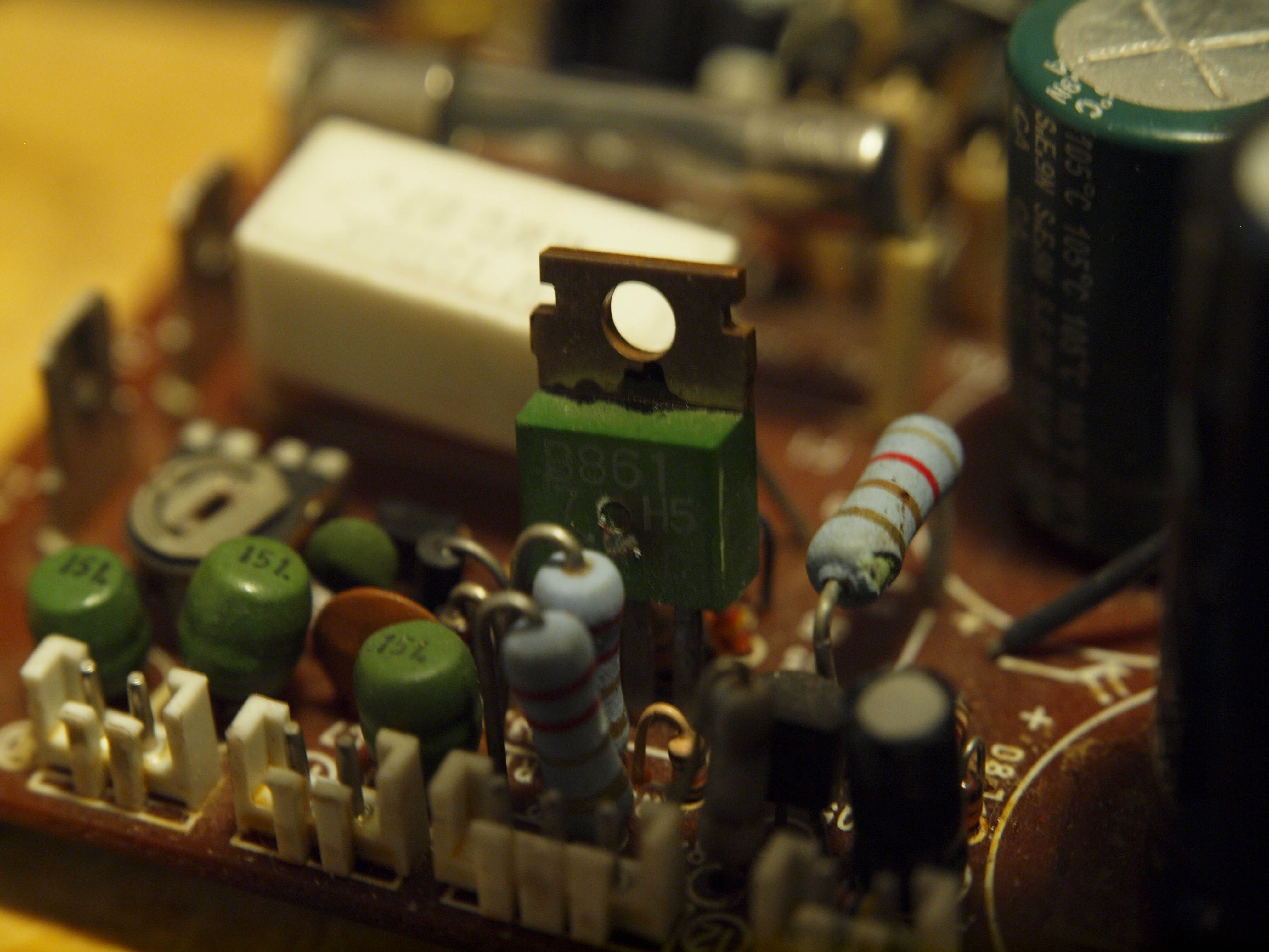
Anyway, eventually something in the power supply fails. It could be the various filter caps (but I recently replaced most of them), there’s a couple zener diode crowbars (which tested OK), there’s some voltage limiting zeners (which failed) and there’s Q101 and Q102… the transistors that take 43VDC and turn it into 28VDC.
Now, there’s two common failure modes for these… they can dump the entire 43VDC into your driver and final transistors. The finals can take it, they’re super rugged and rated higher than that. The driver unfortunately can’t take it… and of course it can no longer be purchased either.
So, first thing was to find out which failure mode occured. Testing the zeners and the transistors showed that some of the zeners failed, especially D3… which failed shorted and Q101 failed open. It also appears that Q1 failed open. I haven’t dug into the final section to test the driver mostly because I’m going to fix this damn rig no matter what. However, if D3 shorts, that should stop Q101 and Q102 from passing all the power to the finals leaving the 22,000uF capacitors to dump their 48VDC all over the semiconductors on the board (which aren’t on the heatsink) thereby cooking any of them that get in the way. The interesting question is why the fuse didn’t blow. It looks like Q1 actually has a scorch mark, though it’s tough to say for sure…
However, I had recently heard that AK6OK was selling a fairly complete and relatively easy to install kit to completely replace the entire PSU with a modern industrial switch mode power supply and a replacement AVR board. Rather than keep heating my shack with an inefficient and marginal linear power supply that I need to fix regularly and could blow up irreplacable transistors at any time, it’s time to drag my TS-940 kicking and screming into the 21st century.
The kit should be here tomorrow, but until then, here’s what I’ve done to prep for the upgrade. If you refer to the schematic above, everything except J110, C101, C102, C103, F101, and S101 has been removed.
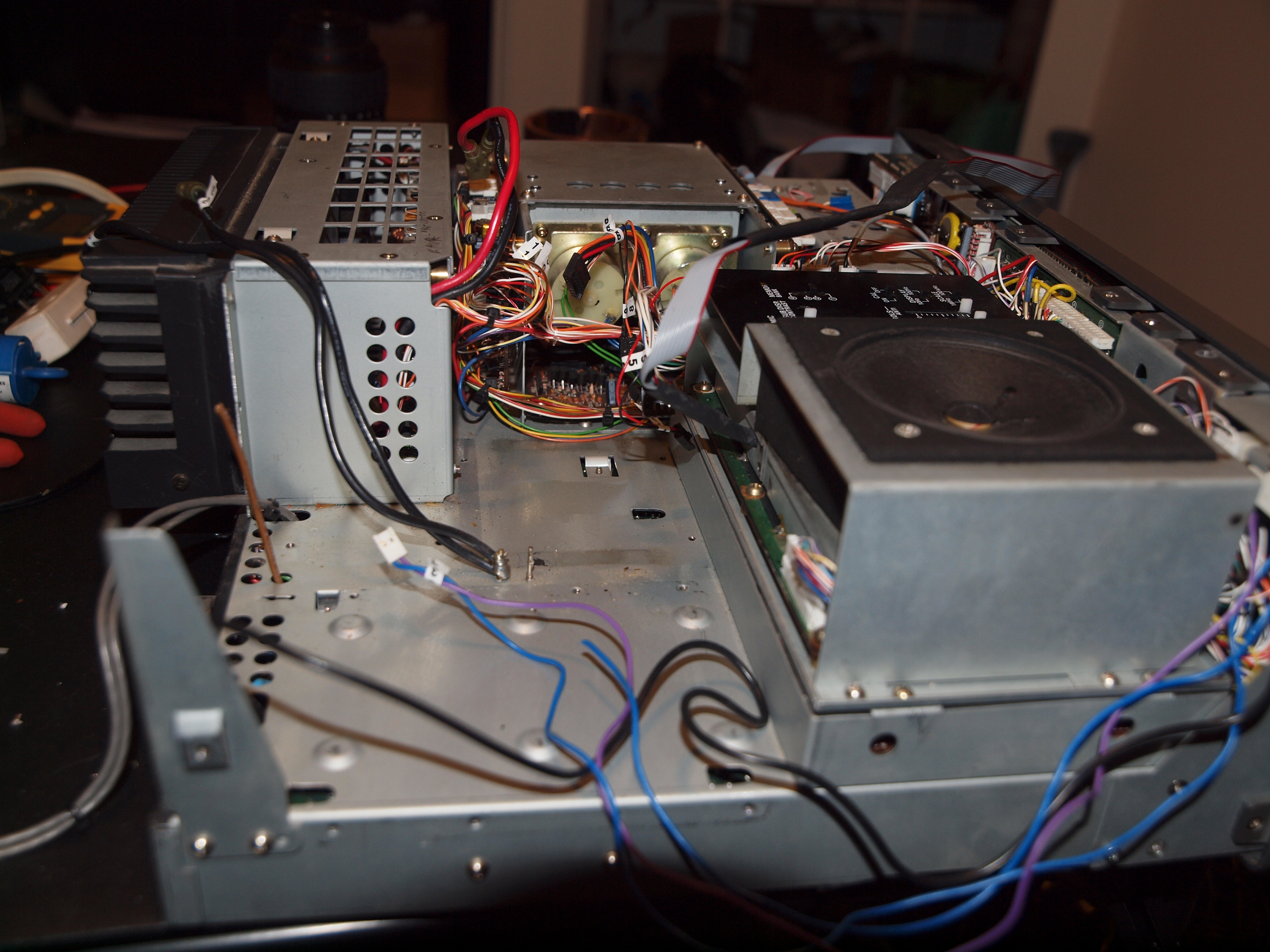
First up, the top side with all the PSU bits removed.
Next up, the pile of stuff that’s been removed.
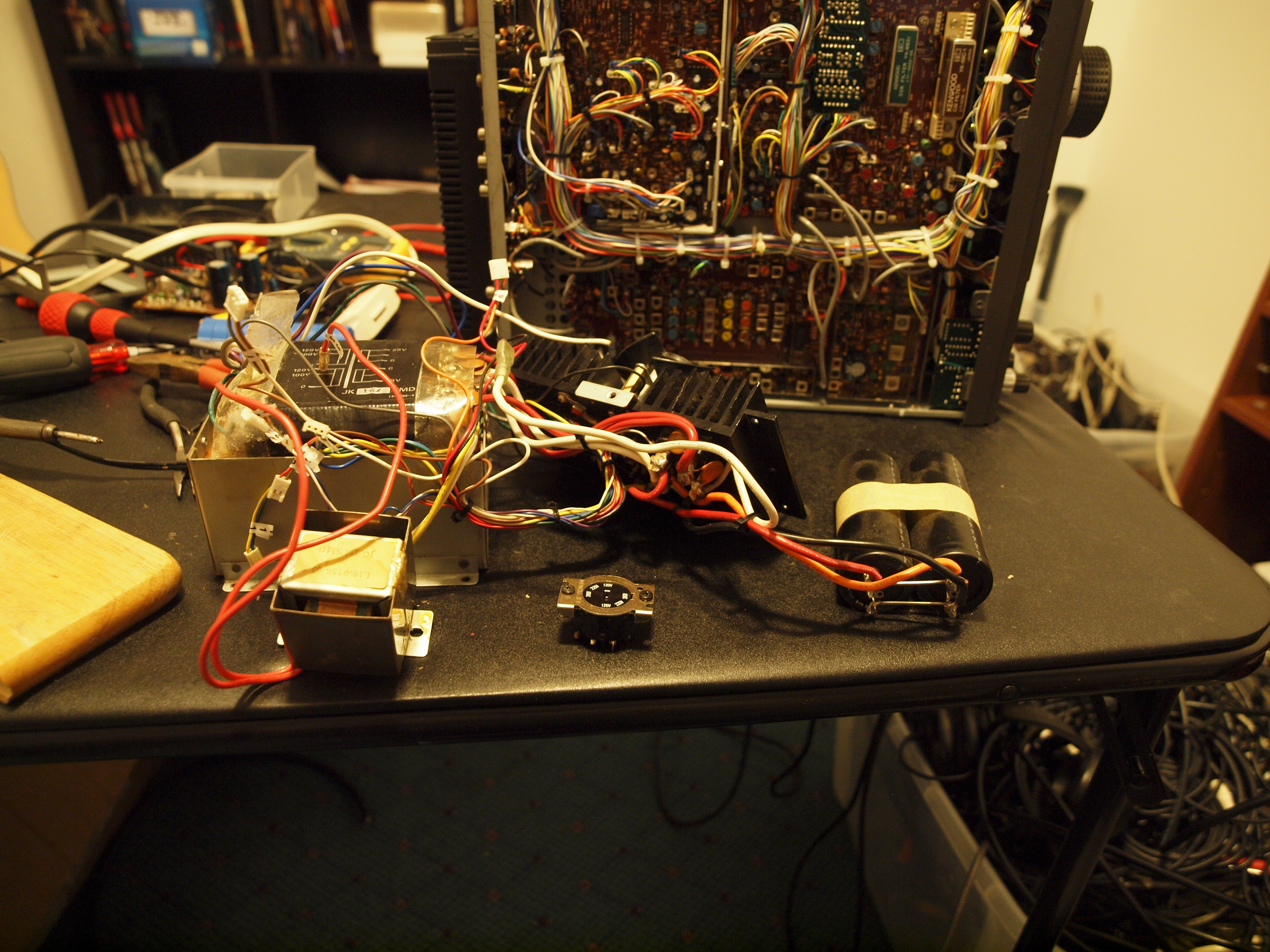
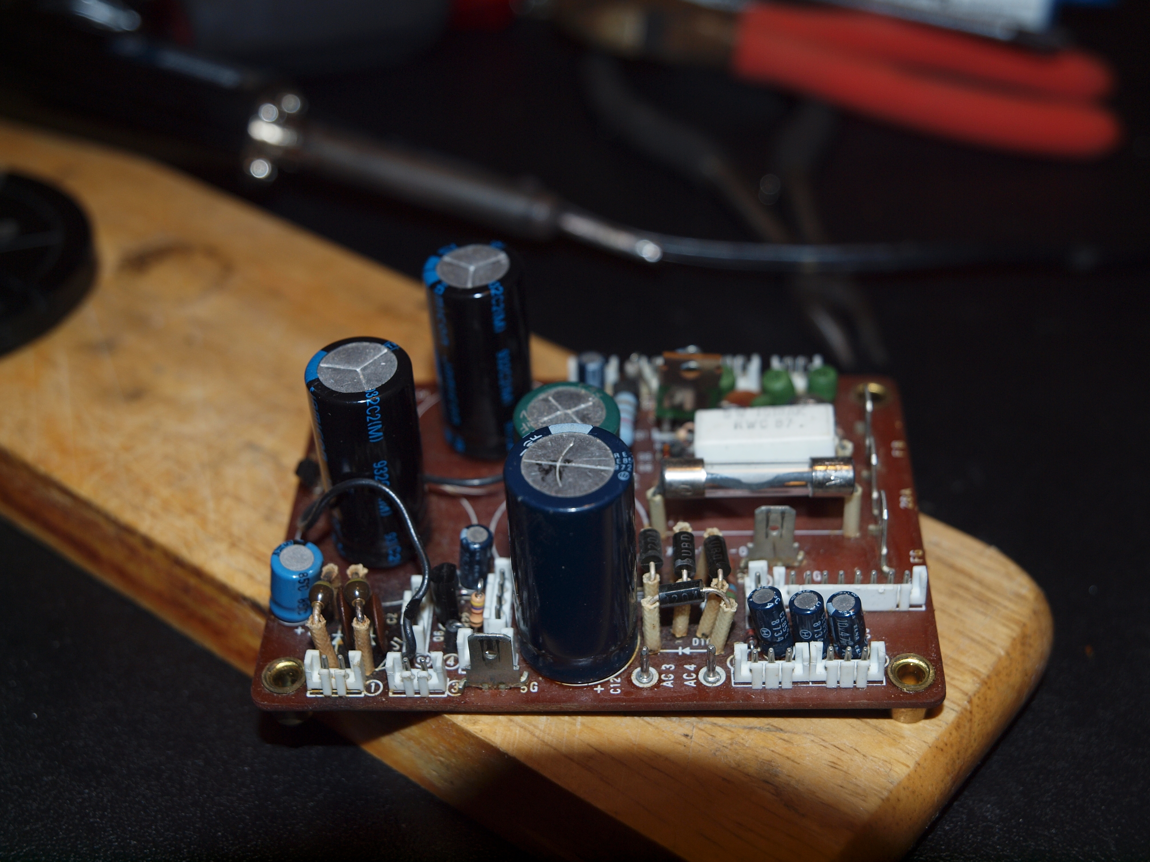
And finally the AVR board (which is almost certainly completely fried)…
Maybe I can sell the old parts in eBay to recoup some of the cost of the PSU upgrade… some people like keeping things original.