|
|
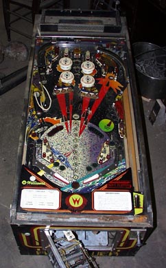
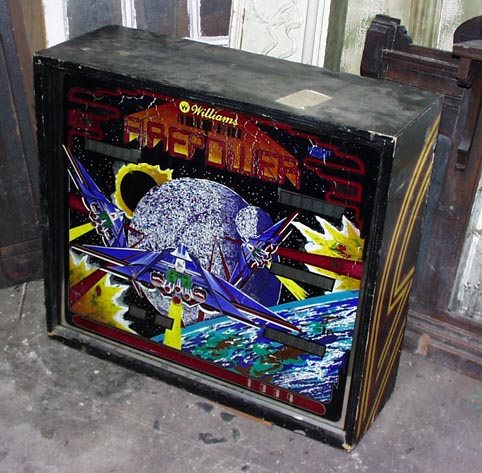
Earlier this year (Feb, 2000), my brother-in-law called to say he had found an old Firepower machine... Was I interested? A month later, I had an old, dirty Firepower. It had been sitting in the back of a furniture repair warehouse for a number of years ( playfield / backbox ).
Well, this is supposed to be about electronics, so we'll skip over the cabinet/playfield issues I dealt with, and move on to repairing the CPU board and making the recently announced Firepower Combo Rom modification/update.
So, first the easy part. I use an older model ART (Applied Reader Technology) EPROM burner which uses a serial interface. I have this hooked up to an old Pentium Pro 200 running FreeBSD where I do all my ROM decoding, programming, testing, and burning. The newer model of this unit is currently sold at Jameco here and an eprom eraser here.
Before going any farther, some nomeclature which I use follows. IC14p20 means Integrated circuit chip pin 20. A [!] character represents NOT. Thus, R/!W represents the Read NOT Write cpu data direction control line. If the control line measures 5 volts (or high), the CPU is said to be requesting data. If it measures 0 volts (or low), the cpu is said to be writing data. Clear as mud now?
Firepower uses GREEN flipper roms. I burned a pair of new 2716 EPROM chips (GREEN1 & GREEN2), even though the old flipper roms were good. The rest of the ROMS on the board did not work. They were all tested by substitution into a Firepower game still using the original roms in all positions.
Next came the COMBO rom. This is a single 2732 EPROM. Since this is the first board to be modified, I had no way to really test the new EPROM other than to read it back out and make sure what was read matched what was originally written. As always, the EPROM was good.
| Crystal CPU inputs |
|---|

|
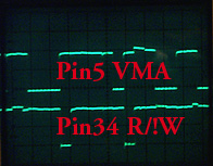
VMA & R/!W @cpu |
|
CMOS Chip Enable lines |
| Not available yet |
In some respects I'm lazy when it comes to board repair. I ohm out every pin of each socket. If any pin measures over 1/4 ohm, I replace the socket. A small amount of resistance turns into a voltage drop, and can cause random (flakey) results on the data or address busses. So, I ended up replacing both sockets for GREEN1 & GREEN2 and also for the new COMBO rom.
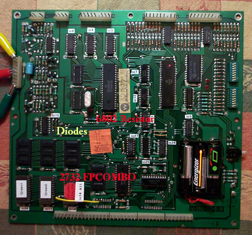
I then started making the mods to the (system 6) cpu board as documented a few months back. Installation of the two diodes (1N4148) is simple. Though hard to see, they are located just at the upper left of the yellow 'D' in the picture. Again, as the instructions say, make sure the banded side of the diodes are towards the TOP of the cpu board. Then I installed the 4.7K ohm resistor on the backside of IC14 from IC14p20 (!CS1) to IC14p24 (+5V). However, I don't like making physical changes to a board, so I didn't cut any traces. Instead, I simply bent IC14p21 up on the COMBO rom. I then soldered the jumper wire directly to the lifted pin, and then over to the IC30p14 solder pad (A11). The jumper is the yellow wire in the picture.
Again, my laziness strikes. If I don't have to use something, I don't. I replaced the 6808 with a 6802 cpu, and made the appropriate jumper change. Thus, I nolonger needed the 6810 ram chip at IC13 since the 6802 contains internal ram. Just to be complete, I also lifted the hard soldered 6810 ram at IC16 (under the 'B' in fpcombo) and installed a socket. Good thing I did. When I tested the removed 6810 it turned out to be bad.
Last but not least, I usually replace battery holders. I stripped off the old holder and replaced it with a new 3 position AA battery holder (this style is available from Mouser as 12BH334). The holder is attached to the board with 2 strips of double sided foam tape.
I use a small switching powersupply for testing. +12volts to pin 1J2-9 (yellow lead), +5 volts to 1J2-5 (red lead), and ground to IJ2-1 (green lead). And? Of course, it didn't work.
Turning the board on produced no LED activity. Using the diagnostic switch produced no results. Well, it had a new 6802 processor, something should be happenning. Debugging time.
I use a small Tek dual channel 100MHz portable scope. I put the probe on:
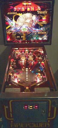
| The Finished Machine |
|---|
|
I then went across all the address and data lines. They all looked good. I then moved out to the bus interface chips. I found a few address lines showing fuzzy results. The long and short of this story? I should have replaced the socket under the cpu. I lifted the old socket and installed a new one. Ok, fine. I replaced the socket under the CMOS ram too. Told you I was lazy.
Hook the test rig back up... two flashes and both LED's are on... progress. However, when pressing the diag switch I get strange results every time. The !NMI line was fuzzy. It turns out that both the SW1 & SW2 were bad. SW1 was reading 100 ohms on the normally closed circuit. SW2 simply wouldn't activate. I only had one spare switch, so I installed it in the diagnostic position, and simply jumpered the normally closed side of SW1 (though this does not appear be needed).
Hook the test rig back up... two flashes and both LED's are on... again... This time, the diag switch causes both LEDs to blink and stay on. Progress. There can be a few things wrong when this happens. (CPU lockup/bad IC14/bad CMOS).
The cpu was not locked up. Everything looked good.
IC14 is the new COMBO rom. Putting the scope on IC10 pin20 showed a nice signal, so IC15 appears ok.
The CMOS setup is a bit more interesting. Checking the logic infront of the CMOS ChipEnable lines gives:
!CE1   IC11 looks good. small but nice trace at pin 6. Note that
            !CE1 is enabled when low.
       IC7  looks good. pin 12 output is the opposite of pin 13.
       IC12 looks good. nice trace at pin 3.

!CE2   straight feed from !RESET -- looks good.

R/!W   Hmmm... this does't look good. Basically, it's sitting at
       5 volts. Check IC27 pins 1 & 2. The traces on these pins
       look ok. Pin 3 is always high. Since we need a 0 or false
       to active Write mode on the chip this doesn't look good.
       Desolder the chip, install a socket, and install a new
       CD4071.
Well, on the test bench the board now boots and goes into diag mode and then the LEDs go out... better. Time to install the board into the machine. It has been mentioned, and is worth repeating, that the program looks for the trough switchs. With the cpu board out of the game, it will not fully boot.
After installing the CPU board and turning it on, test 04 mode is entered immediately upon powerup. Cool. Hit the diagnostic switch once, blinks and then the LEDs go off. Turn the machine off and back on and it boots up into game over/attact mode.
One more working board, using new EPROMS. Information on this modification to the System 6 CPU board as provided by Williams can be found here.