Simplified Kenwood TS-850 AM modifications
Written by:
Bill Paul N1GPT wpaul@windriver.com
The Kenwood TS-850 is well known for being able to produce exceptional SSB audio, when used in conjunction with the Kenwood DSP-100 accessory unit. I'm fortunate enough to own this combination, and I really enjoy it. Unfortunately, it isn't as effective on AM: it does produce fairly clean audio, however while it does noticeably improve low-end frequency response, it doesn't help as much for high-end response. The design of the DSP-100 is such that it is responsible for generating the carrier for AM. Normally, to achieve wide frequency response on SSB, you would turn off the low and high pass filters in the DSP-100 entirely, by setting some of the DIP switches on the rear panel. For AM, you can turn off the high pass filter (which improves bass response), but turning off the low pass filter also disables the generation of the AM carrier. I don't believe there's an easy way to override this.
As a result, the recommended approach for achieving hi-fi AM audio from the TS-850 is to simply forgo the DSP-100 completely and inject audio directly from a professional audio processing rack into the balanced modulator stage. This works, but it has a couple of drawbacks. For one, you'll need an audio transformer to connect the low impedance output from professional audio gear to the high impedance input of the modulator, and transformers that provide the best dynamic range with least distortion are expensive. Also, this modification will bypass the VOX circuitry, making VOX operation impossible when using the hi-fi input. Lastly, if you intend to use the radio for SSB (with the DSP-100) and/or FM too, you'll still need to feed audio through the standard mic connector, which would require either changing the mic cabling when switching modes, or rigging up a second output from your audio chain.
However, there is, in my opinion at least, a simpler and cheaper way to achieve hi-fi AM audio that avoids these drawbacks.
It should be noted that one of the reasons cited for injecting audio directly into the modulator is that it bypasses the mic pre-amp circuit in the TS-850, which is claimed to be the source of some distortion. I can't dispute this, however in my experience, whatever distortion may be present is not serious enough that it can noticed over the air, especially under typical operating conditions where you may have to contend with fading, interference, atmospheric noise, and who knows what else.
There are three basic issues that need to be addressed in order to improve AM audio quality:
1) High end frequency response
2) Low end frequency response
3) ALC action
All three of these will be addressed below. For reference, I recommend downloading and studying the TS-850 Service Manual, which you can obtain at the following link:
If you own a TS-850, you should already have a copy of the owner's manual. If not, you can download a copy from here:
High-End Audio Frequency Response
High end response is limited by filtering. The Kenwood TS-850 is popular among hi-fi audio enthusiasts largely because of its flexible filtering controls. The TS-850 uses two IF stages, at 8.83Mhz and 455Khz. From the factory, the filtering for the receiver at both stages can be controlled from the front panel using two buttons, which allow the operator to cycle through the available filters at each stage. For the 8.83Mhz IF, the operator can select 2.7Khz, 6Khz or turn off the filter completely. At 455Khz, the operator can choose between 2.7Khz, 6Khz or 12Khz. Unlike the 8.83Mhz IF, the filtering for the 455Khz IF can't be turned off entirely. At least, not normally. Additional filter configurations may be available if you've installed the optional narrow SSB or CW filters.
By default, the filter controls only allow filter selection to be set manually for the receiver. The same filters are used for transmit too, but the selections are not configurable: the radio always chooses a pre-set filter option based on the mode (2.7Khz for SSB, 6Khz for AM).
Fortunately, there's a way to override this default behavior: it's possible to enable filter selection on transmit using an extended option menu. The procedure to do this is as follows:
1) Turn the radio's power supply on, but keep the radio off
2) Press and hold the SCAN key and the TX M.CH key, while turning the radio on (there are two M.CH keys, one for RX and one for TX; only the one for TX will allow you to access the extended option menu)
3) You should see a 4-digit hexadecimal value in the frequency display -- this is the ROM checksum. You will also see the number 00 to the left of the display, in the memory channel selection window. This number indicates the configuration option.
4) Rotate the small encoder knob to select option 01. The word "off" should become visible in the display.
5) Press the 1Mhz step up (^) key -- the radio should beep and the display should now say "on"
6) Press the CLR key on the number keypad to save the settings and exit the menu. The radio should now be back to normal operation.
All the extended menu options are described on page 35 of the Kenwood TS-850 Service Manual.
If you want to reverse this change, you can either do a CPU reset (hold the A=B button while turning on the radio), or repeat the above procedure, except in step 5, press the 1Mhz step down (v) key instead. This should change the setting from "on" back to "off."
Once this change is done, you will be able to use the filter selection controls while transmitting as well as while receiving. The radio will remember the selection for each mode separately.
Note that if you don't have the DSP-100 unit, you should be careful how you set the filters for SSB operation. If you do have the DSP-100 and turn the 8.83Mhz filter off, you'll get 6Khz wide audio. If you don't have the DSP-100, you'll still have very wide audio, but you'll end up transmitting in double sideband mode. To avoid this, you must keep at least one of the filters set for 2.7Khz at all times. (I suggest leaving the 455Khz filter at 2.7Khz.)
For AM, best results can be achieved with both the 8.83Khz and 455Khz filters off completely, but remember that normally the 455Khz IF filter can't be turned all the way off. There is a way to effectively disable it though:
1) Turn the radio over
2) Remove the two screws from the filter access panel, and open it
3) Find the slot for the optional 455Khz IF CW filter
4) Place a jumper wire from pin 2 on one end of the filter connector to pin 2 on the other
5) Replace the access panel and screws
6) Turn the radio right-side up again
7) Open the little door at the left rear corner of the radio
8) Find the small DIP switch block
9) Set switch 1 to ON -- this will enable the option 500Hz filter selection for the 455Khz IF
9) Close the door
This modification is illustrated on the CleanRF.com site. A photo of the installed jumper wire is shown below:
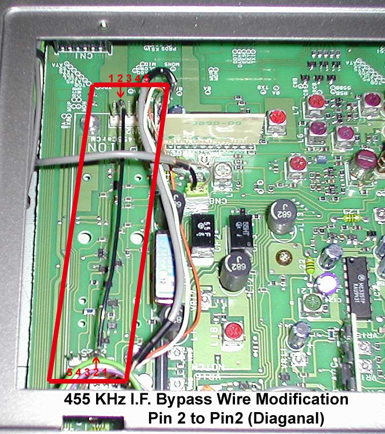
Placing a jumper wire in the optional filter slot allows you to use the optional 500hz narrow filter selection as a "bypass" mode, effectively disabling all filtering. This can yield up to 10Khz of response. In my case, I happened to have a calibration cable from another radio that turned out to be perfect for jumpering the pins without having to do any soldering.
Note that the DIP switch settings are documented on page 76 of the TS-850 Owner's Manual as provided above.
Low-End Audio Frequency Response
The Kenwood TS-850 uses an AN612 balanced modulator chip for AM and SSB. Kenwood has used this same chip in many of their HF radios, including (at the very least), the TS-430, 440 and 450/690. In most cases, the audio input of the AN612 is fed from a single-transistor buffer stage, with a 0.1 uF capacitor in between. (There are DC voltages both on the AN612 input pin and the collector of the buffer amp, so the capacitor is needed to provide DC isolation.)
It turns out that not only is the AN612 modulator common to many Kenwood radios, this 0.1 uF capacitor is too. Several articles have been written describing methods for improving AM audio quality of the Kenwood TS-440, many of which mention this 0.1 uF capacitor as the primary source of low-end audio roll-off. There are other capacitors in the audio path which are also a factor, but this one is the main choke point. In particular, after being inspired by the information presented on this page, I checked the TS-850 schematics and found that it shares this same design aspect with the TS-440. This particular article recommends using a 1 uF capacitor instead. I decided to make this same change to my TS-850.
On the TS-850, the AN612 modulator chip is IC3 on the IF unit. It can be seen on page 157 of the TS-850 Service Manual. Pin 1 of IC3 is fed from the collector of Q26, though C144, which is 0.1 uF.
C144 is a surface mount part, on the component side of the IF unit. Q26 is also a surface mount part, but it's on the foil side. In my radio, I've added the 1 uF electrolytic capacitor in parallel with C144, by soldering it to the foil side of the board, with the negative terminal connected to pin 1 of IC3 and the positive terminal connected to the collector of Q26. There's only about half a centimeter of clearance between the foil side of the IF unit and the chassis of the radio when the board is in place, but I was able to find a very small 1 uF capacitor that fit with a few millimeters to spare. Those more adventurous than I may chose to solder the capacitor directly across C144 or just replace it outright, however I did not have access to SMT soldering tools at the time I did the modification, and was concerned about applying too much heat to C144 or damaging traces on the board by clumsily trying to remove it.
The photo below shows the foil side of the IF unit, with the balanced modulator audio injection modification applied:
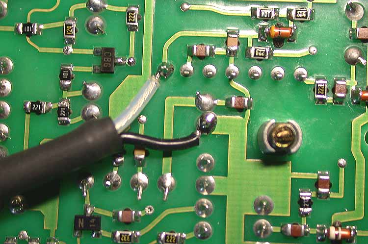
(We don't actually want to perform this mod, however this photo clearly illustrates the component layout, and is better than any I was able to take myself.) The center conductor of the coaxial cable (the one with the clear/white insulation) is soldered to pin 1 of IC3. Immediately to the left is the Q26 (black, labeled 'CBG'). To the right of the collector tab (the middle pin) is a second solder joint. This is a plated-through via that leads to the component side of the board, where C144 is mounted. The negative lead of the 1uF capacitor should be soldered to pin 1 of IC3, and the positive lead can be soldered either directly to the collector of Q26, or to the via right next to it.
Getting the IF unit out in order to work on it can be a bit of a challenge. There are many ribbon cables, wiring harnesses and coax cables connected to it. I suggest taking pictures of the board with a cell phone or other camera before you begin attempting to remove it, so that you'll be able to tell what connections go where when time comes to re-assemble the radio. Pay particular attention to the three coaxial cable connectors: they're color coded, but it's easy to lose track of where to plug them back in once they're out.
When lifting out the board, you will find that it may be partially blocked in by the cable harnesses running along the front of the radio. You should eventually be able to slide it free; just be patient and avoid using too much force.
Note that since AN612 is used for both AM and SSB, this modification will have the effect of increasing low end response for SSB operation as well, without requiring the DSP-100 unit.
ALC action
From the factory, the TS-850 is calibrated such that the ALC action in AM mode is very aggressive. Even if you turn the power control all the way up, the ALC meter will still show the ALC kicking very heavily in when modulating. This makes it nearly impossible to achieve positive modulation and introduces distortion. This behavior is very common among solid state HF transceivers with low level modulated AM.
In some cases, you can defeat the ALC action by introducing an ALC voltage via one of the accessory connectors in the back of the radio. With the TS-850, there's an alternative. Per page 108 of the TS-850 Service Manual, VR7 on the RF unit can be used to adjust the ALC level. This can be used to widen out the range of the power control on the front panel (which is also an ALC control). VR7 is located under a metal RF shield near the back of the radio. There are holes cut into the shield to allow access to the adjustment points, however I found it easier to just temporarily take out the shield. This can be easily done by removing the two screws on either side and sliding it out towards the front of the radio.
After removing the RF shield, turn VR7 slightly counter-clockwise. The adjustment is very sensitive, so only a small change (maybe a millimeter or so) should be required. A plastic calibration tool is recommended, however a metal jewler's screwdriver will also work if you make the adjustment with the radio powered off.
It should now be possible to defeat the ALC action entirely when operating in AM mode by turning the power control all the way up. Keep the carrier control set at around 25 watts. It should still be possible to adjust the power control down to the point where the ALC kicks in again, if you desire.
Be aware that this affects the behavior fo the power control on all modes, not just AM. When operating in SSB mode, be careful to keep the radio adjusted so that the ALC action is still present, as recommended by the manual.
Results
Kenwood recommends setting the radio for a 40 watt carrier when operating in AM mode. In reality, it's best to lower the carrier to around 25 watts instead. In order to achieve 100% modulation with a 40 watt carrier, the radio would need to sustain 160 watts of power on modulation peaks. This is a little beyond the upper limits of the final amplfier stage. I tested my radio by feeding a sine wave from the signal generator on my Kenwood SM-230 station monitor into the audio input and observing the resulting wavefrom on the scope. I found that with a 40 watt carrier, the negative modulation peaks of the sine wave would descend all the way to the 0 volt line, but the positive peaks would only extend about 85% in the positive direction. The waveform was not flattened, but it was being limited. With the carrier reduced to 25 watts, the positive and negative peaks were much more symmetrical.
I use a Behringer B1 microphone with my TS-850, along with a Behringer Xenyx 502 mixer, Nady 31-band single-channel equalizer, and a a Behringer Autocom XL MDX1600 audio processor. I typically keep the mic gain control on both the radio and the DSP unit set at about the 9 o'clock position (about a quarter of the way open). I consistently get very good audio reports on AM. In many cases, other operators were unaware that I was using a 'plastic' radio until I told them. Overall, I've been very pleased with the results. It should be possible to apply similar modifications to the TS-450 and TS-690, and possibly the TS-950 radios as well.
If you have any questions, feel free to e-mail me or contact me through QRZ.com.
73, -Bill N1GPT